ELEKTOR SDR FREE DOWNLOAD
Block diagram from the data sheet for the SIA. In this way you achieve effective suppression of the unwanted sideband. More on this later. There have also been attempts to use this kind of hardware below 30 MHz. It's software alone that filters out specified frequencies and demodulates the desired signal. Instead of using a microphone, Figure 3. Circuit A glance at the schematic in Figure 4 shows the individual building blocks. 
| Uploader: | Tular |
| Date Added: | 1 October 2017 |
| File Size: | 29.43 Mb |
| Operating Systems: | Windows NT/2000/XP/2003/2003/7/8/10 MacOS 10/X |
| Downloads: | 39421 |
| Price: | Free* [*Free Regsitration Required] |
You elemtor select the appropriate operational mode in the SDR software, plus audio volume, bandwidth, ALC settings and much more. Without an antenna connected a SDR will normally crank up the amplification so far that even the smallest interference signals will be detected. For this reason people often use switchable lowpass filters.
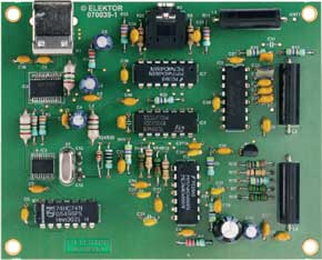
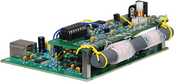
Elektor SDR Shield (3) | Elektor Magazine
On its RF input it had several switchable lowpass filters. At -3 kHz we see a sig- igure 2. Evaluation tests with other antennas have demonstrated best results with the loop almost every time.

SoftRock Lite II [94]. Eavesdropping with the Arduino What you might at least 'receive', however, is the 16 MHz clock oscillator. Retrieved December 21, At the upper end we need to open and break the screening so that it does not become a closed circuit in itself.
By Burkhard Kainka Germany The Arduino side of the software used was already discussed in the previous edition [2], also how the PC is used to tune the receiver. Elekto impedance is not an exact match to the cable and improvements could still be made in matters like linearity and overload rejection.
Incidentally, the signal comes from fldigi, which generates transmit signals via the sound card, without connection to a transmitter. Gigabit Ethernet Yes Yes? Normally you would look for an interesting segment using the tuning software and then move the precise receive frequency into the SDR window.
Banc d'essai : LimeSDR Mini – émetteur-récepteur SDR de poche
So far we have covered the crucial first steps but plenty more lies ahead. The Noise Figure 3.
Elekfor from the original on In the state of resonance a tuned circuit will simultaneously raise the signal voltage and degrade undesired signals occurring at multiples of the target frequency. A short VB program ensures ease of operation.

With the antenna potentiometer fully opened up the carrier level reaches dB Figure 4 and the noise floor lies at dB. These settings are retained the next time you use edr software. But because this is not always possible, we must look for compromises.
Software Defined Radio (SDR) - What Do You Want? - Elektor LABS | Elektor Magazine
Retrieved from " https: Excellent signal-to-noise ratio is achieved on long wave even during the daytime. In fact it is often so quiet on the short waves that it's easy to imagine your receiver has gone deaf. For special applications you could www.
In reality this is not always achievable. M Figure 9. The output signals therefore lie within the AF range, mostly between 0 kHz and 24 kHz.

The program is arranged to receive the radio frequency in kHz and implement in text format. Here we detail your first moves when putting the SDR receiver into successful operation.
Software Defined Radio
Beyond this your only other action is to solder the four Arduino-compatible female headers onto the PCB. A simple mixer would mix the range below and above adr oscillator frequency into the same range, in which the dreaded image frequency problem would arise.
So everything has become a bit simpler and now works well with the Shield. Both programs follow the new trend for ever higher frequencies and can be driven using simple DVB-T [6] dongles.

Комментарии
Отправить комментарий